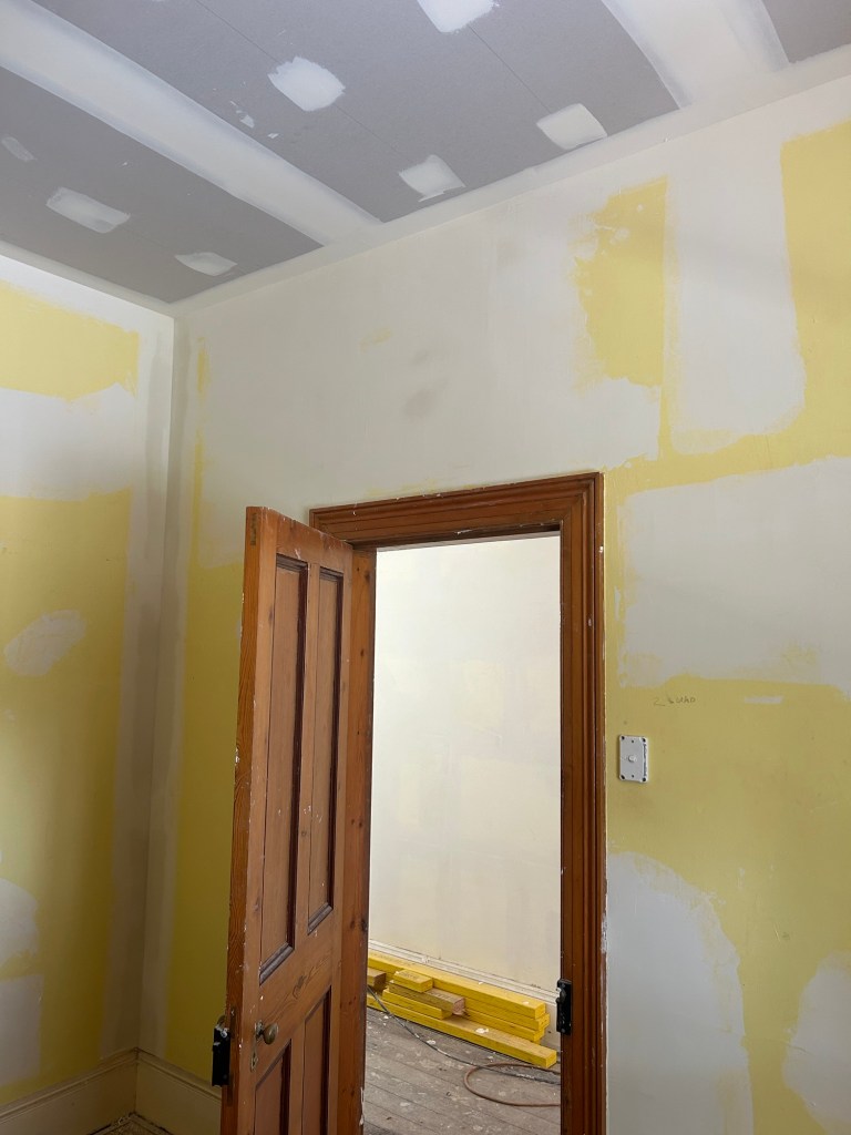
BEFORE and AFTER heritage plastering Launceston Tasmania. Newstead Plastering
#hertiageplasterer #heritageplastering #philthecracks #plasteringlaunceston #launcestonplastering #plasteringtas #newsteadplasterer


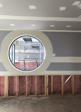
BEFORE and AFTER heritage plastering Launceston Tasmania. Newstead Plastering
#hertiageplasterer #heritageplastering #philthecracks #plasteringlaunceston #launcestonplastering #plasteringtas #newsteadplasterer
I love it when technology creates a work environment which enables a plasterer to last longer in the trade. This new sander saves the arms from getting a real workout when sanding internals and square set manually with a sanding block. Love this product purchase.
#newtool #stealthsander #tapepro #tapeprostealthsander #philthecracks #launcestonplastering #launcestonplasterers #plasteringtasmania
Attribution: Wallboard Tools instruction video
#sheffieldplastering #newhomeplastering #newbuildplastering #plasteringtasmania #philthecracks #plastering #plasterer
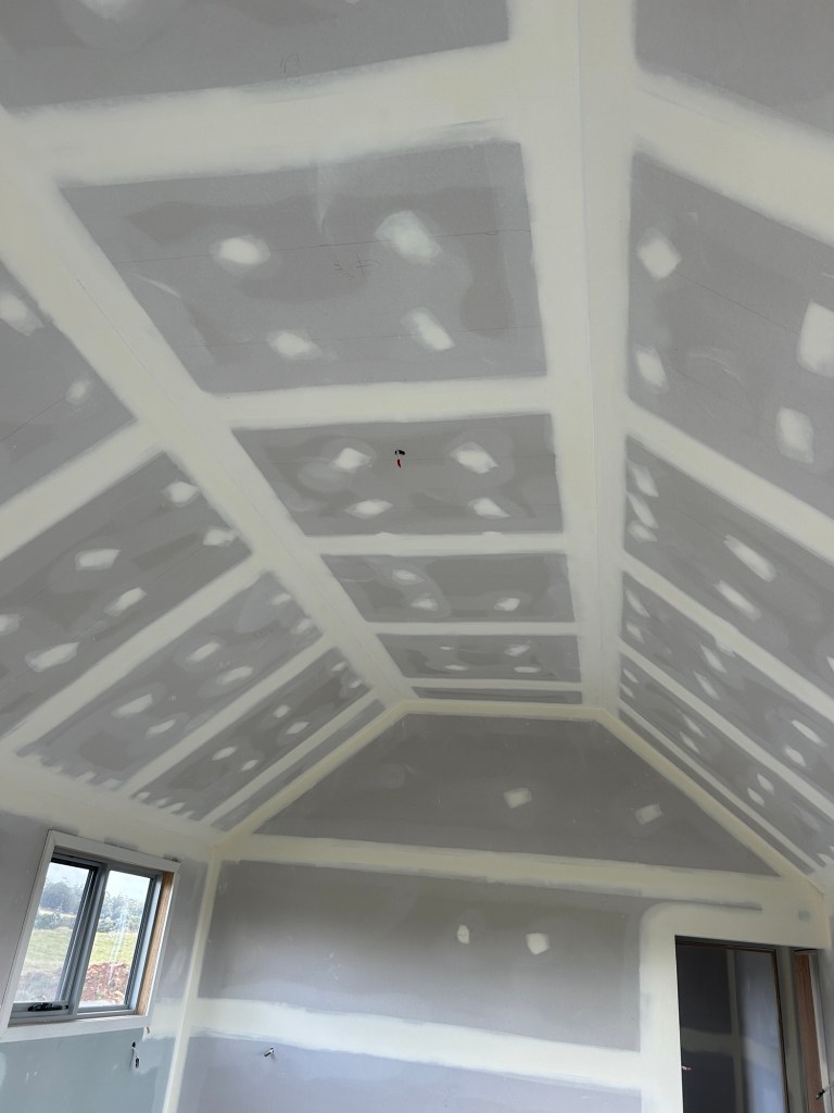

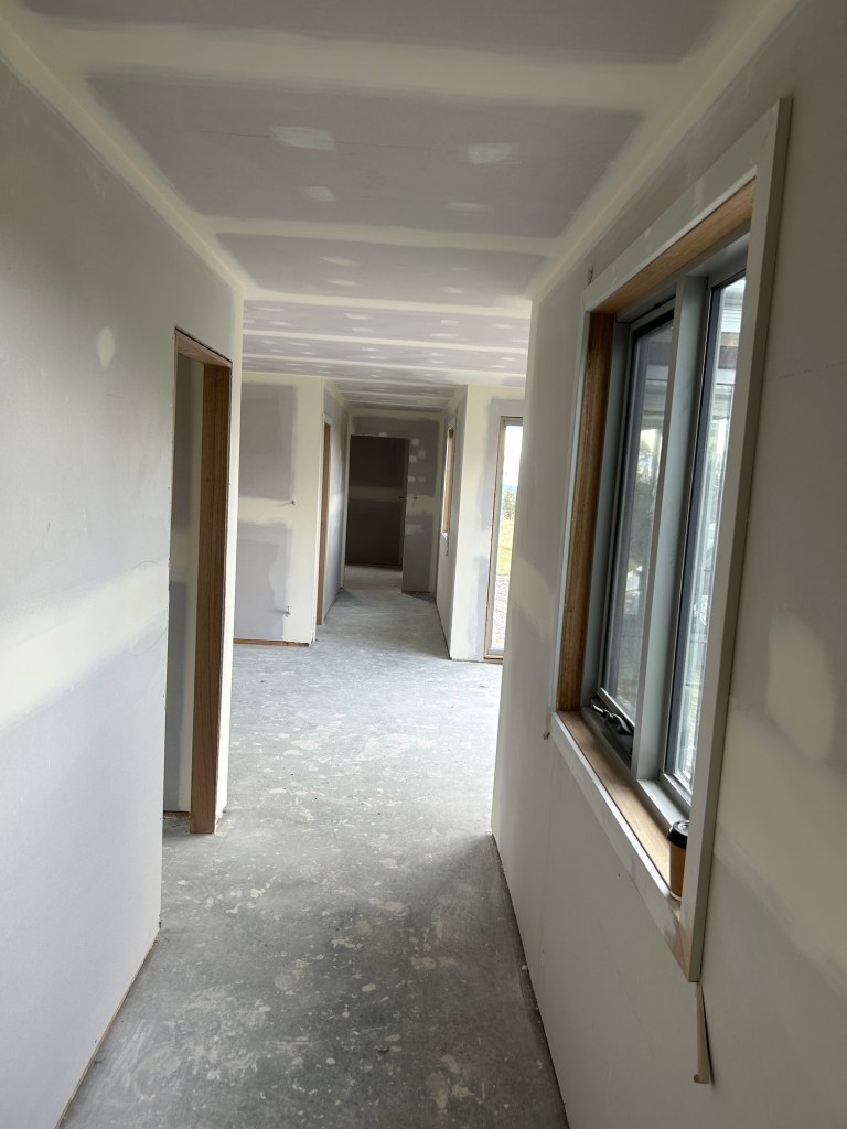
#newhouseplastering #eastcoastplasterer #scamanderplasterer #plasteringtasmania #newbuildplastering #plasterertas


Plasterboard can be cut by scoring the face linerboard with a knife and snapping the plasterboard back away from the scored face.
Always score the front (non-printed) face first. The back linerboard can then be cut from the back towards the front. Impact Board has fibreglass mesh behind the back face paper, so this face must also be cut before snapping.
Alternatively a saw may be used from the front face.
Cut edges are to be smoothed as required to permit neat joints. A metal T-square will assist in creating a clean, straight cut.

